

Supercapacitors and insertion batteries: what are the differences?
Latest updated: November 15, 2024Introduction
Supercapacitors and insertion batteries are currently the most widely used devices for electrical energy delivery/storage. While insertion batteries are used for energy delivery/storage, supercaps are used for power delivery/storage, as can be seen in the Ragone plot below. In this article, we will try to describe and explain the different characteristics of each type of device.

Capacitors have been around for ca. 150 years [1] and are mainly composed of a non-conductive dielectric material (ideally vacuum) sandwiched between two electrical conductors. In the 1950s, porous electrodes and electrolytes were introduced, which allowed for much more charge to be stored, compared to classical capacitors. In 1975, studies by Conway on underpotential deposition of H on Pt or oxidation/reduction of RuO2 led to the term “supercapacitor” (SC) [2].
Because electrochemical reactions occur in supercapacitors, they are often confused with battery cells, in this article we want to clarify where the key differences and similarities lie between the two.
Definitions
Many articles exist in the literature that delve in detail into the differences between supercapacitors (SC) and battery cells. A non-exhaustive list of these articles includes a review from 1991 by Conway [2] and more recent articles by Simon et al. [3] and Costentin et al. [4].
As mentioned in the introduction, capacitors are composed of two electrodes separated by a dielectric insulative material. This material can be polarized, meaning an electrical field can be established across it. Its main property is to allow electrical charges of opposite signs to be accumulated on each plate or electrode. Historical dielectric materials were glass, porcelain or paper. At the end of the 19th century, the first electrolytic capacitors were invented, made of aluminum plates with a stable oxide layer in an alkaline medium [1]. Although capacitors had been used for energy storage since the 1950s, research in the 70s lead to a breakthrough in capacitors that could store much more energy per volume and the term “supercapacitors” (SC) was coined.
As can be seen in Figure 1, there exists many different types of capacitors and energy storage capacitors are only a small portion of them.
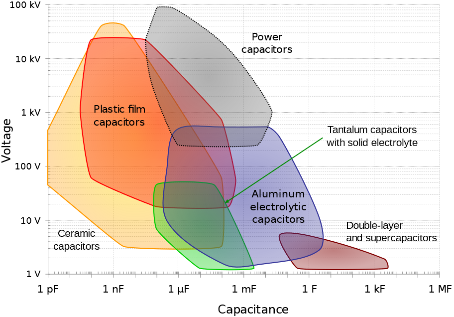
Figure 1: The different types of capacitors and their main characteristics (from [5]). In general, capacitance and voltage correlate with physical size and cost.
Figure 1 helps us to summarize the various types of capacitors:
- dielectric capacitors (like ceramic and film types)
- electrolytic capacitors (like aluminum and tantalum types)
- (electrical) double-layer capacitors (EDLCs)
- supercapacitors (electrochemical or pseudocapacitors [1])
Figure 1 follows the convention of Conway’s paper [1], where supercapacitors are separated from EDLCs and denote electrochemical pseudocapacitive capacitors, where electrochemical reactions occur.
More recently [5-7] the term “supercapacitor” was used to refer to both EDLCs and pseudocapacitors. It was also proposed [3] to use the term “supercapacitors” to refer to EDLCs (which are considered to be electrochemical capacitors as well) and “oxide supercapacitors” to refer to electrochemical pseudocapacitive supercapacitors. To add even more confusion, the term “ultracapacitors” is also sometimes used and hybrid supercapacitors, including both EDLCs and pseudocapacitors [6], are claimed to combine the best of both batteries and supercapacitors: high specific energy combined with long cycle life and short charging times [3].
Terminology aside, supercapacitors are capacitors specifically used to store energy, as opposed to the more traditional usages of capacitors in electronics (power supply stabilization, periodic signals processing, signal filtering…) [7].
For the rest of the article, a basic knowledge of how a battery cell operates is required. However, you have access to basic concepts of batteries by browsing through these articles: “Anode vs Cathode: What’s the difference”, “Battery states: State of charge (SoC), State of Health (SoH)”, “How to avoid side reactions during battery charging/discharging?”, “Battery science: Interactive glossary of terms”.
Capacitive and Faradaic current
In electrochemistry, whatever the considered system, the total current $I$ resulting from a polarization or a voltage $U(t)$ is [8]:
$$I=I_\text c + I_\text f\tag{1}$$
With $ I_\text c$ the capacitive current and $I_\text f$ the Faradaic current.
The capacitive current depends on the time-derivative of the voltage $U(t)$ and the capacitance $C$:
$$ I_\text c=C\left(\frac{\text{d}U}{\text{d}t}\right) \tag{2}$$
In the specific case of a voltage sweep at a scan rate $\nu$, $\text{d}U/\text{d}t=\nu$ and:
$$I_\text c=C \nu\tag{3}$$
The Faradaic current expression is much more complex and generally depends on kinetic factors related to electron transfer and on the interfacial concentrations of electroactive species.
In the systems that are considered here (supercapacitors and batteries), we can pick two relevant electrochemical mechanisms:
- a surface Faradaic process, the electrosorption, or homogeneous insertion [9, p. 335]
- a volumic or thin film Faradaic process, the restricted diffusion, or insertion [9, p. 347]*The electrosorption is a limit case of the insertion process as is described in [9] .
These two types of current helps us in discriminating two types of devices: devices where the current is only capacitive and drawn from charge displacement (capacitors, EDLCs), and devices where their current is Faradaic and is drawn from electron transfer between ionic charge species and an electronic conductor (pseudocapacitors and batteries).
A simplified illustration of the charging process for each device is presented in the next part.
Devices and processes
Dielectric capacitor
In a dielectric capacitor, the current is only electronic. Between the two poles of the capacitor, electrons flow as is shown in Figure 2. A capacitor is usually symmetrical, meaning either of the two electrodes can be polarized negatively or positively, depending on current direction.

Figure 2: Depiction of the charging process of a symmetric dielectric capacitor
Electrolytic capacitors and EDLCs
Electrolytic capacitors and EDLCs, compared to dielectric capacitors, have an electrolyte separating the two electrodes. The electrolyte contains charged ionic species, that are displaced during the charge or discharge cycle (Figure 3).

Figure 3: Depiction of the charging process of a symmetric electrolytic capacitor or an electrical double layer capacitor (EDLC).
The only difference between an electrolytic capacitor and an EDLC is the amount of charge that can be accumulated for a given mass and the operating voltage, and hence how much energy and power they can store.
Batteries
As previously stated, we are only considering insertion batteries in this article, where ionic species are not only transported through the electrolyte separating the two electrodes, but they are also being oxidized or reduced at the electrodes surface (Fig. 1). A battery cell is not symmetrical, one electrode is positive and one negative and once reduced the positively charged ionic species diffuses inside the electrode until it meets the current collector. This simplified process is called direct insertion or direct restricted diffusion.

Figure 4: Depiction of the charging process of an insertion battery.
In a battery cell, the insertion material is a volumic (three-dimensional electrode) or thin film electrode composed of an aggregation of particles, in which diffusion occurs sluggishly in different modes and directions. The volumic electrode ensures that a large number of atoms can be intercalated and consequently a large amount of energy converted. The diffusion processes can be so complicated, and the electrode so thick, that the inserted species never reach the current collector. In this case, in which insertion is limited, the diffusion in the host material is semi-infinite.
Pseudocapacitors or supercapacitors or electrochemical capacitors
Keeping the insertion process of a battery in mind, let us consider another limiting case, where the electrode is so thin that it can only contain one layer or a few layers of atoms. This is depicted in Fig. 5, where there is an electrochemical reaction and a very fast diffusion in the electrode. This process is called homogeneous insertion and it is the process at stake in a supercapacitor. There are no concentration gradients of intercalated species in the host material. Consequently, charging and discharging occurs more rapidly than in an insertion battery, which means supercapacitors exhibit a larger power than for batteries. The number of inserted atoms depends on the contact surface of the electrode and not on its volume (Fig. 5).

Figure 5: Depiction of the charging process of a supercapacitor, where homogeneous insertion occurs.
It should be noted that this process is analogous to the electrosorption or electroadsorption reaction, depicted in Fig. 6.

Figure 6: Depiction of the charging process of a supercapacitor, where electroadsorption occurs.
Depending on the technology used, the electrochemical process in a supercapacitor may tend toward a non-limiting case of the insertion reaction.
Hybrid supercapacitors
Hybrid supercapacitors combine EDLCs and supercapacitors, i.e. capacitive and Faradaic processes. Hybrid supercapacitors are generally non-symmetrical and combine both an EDLC electrode on one side and a pseudocapacitor electrode on the other side. Some manufacturers even claim that hybrid capacitors are a combination of a Li-ion battery and an EDLC [10].
To know more about the differences between Faradaic and non-Faradaic current, please see the open access paper by Biesheuvel et al. [11].
In the next paragraph a table will summarize the major differences between capacitors and batteries.
Comparative characteristics of capacitors, EDLCs, supercapacitors and insertion batteries
Specific energy and power are defined in the Battery glossary:
The specific power, often incorrectly called power density, is the capability to deliver power per mass $m$.
$$ p=\frac{P}{m}\tag{4}$$
The (practical) specific energy is the total electrical energy (?) divided by the mass $m$. This quantity is often incorrectly called (practical) energy density. The specific energy is frequently given in W h kg-1.
$$w=\frac{W}{m}\tag{5}$$
The following relationships should also be remembered:
$$P=UI\tag{6}$$
$$W=UQ\tag{7}$$
Where $Q$ is the electric charge.
$$P=\frac{W}{t}\tag{8}$$
Where $t$ is the time
Ragone plots are used to compare the performance of each device [13]. Thanks to the details given above you can now better understand why capacitors, EDLCs and supercapacitors are used for high power applications and why batteries are used for high energy applications: on one side processes are fast, so the discharge/charge time is short and the power high; on the other side the electrical charge is large, so the energy is also large.
| Device | Usage/ Applications | Typical data | Electro-chemical reaction | Transport process | Charge rate | Typical Cyclic Voltammetry shape | Typical Nyquist EIS graph |
|---|---|---|---|---|---|---|---|
| Capacitors | Power supply stabilization, periodic signals processing, AC and DC current separation, memory… | Capacitance from nF to µF | No | No | Fast | 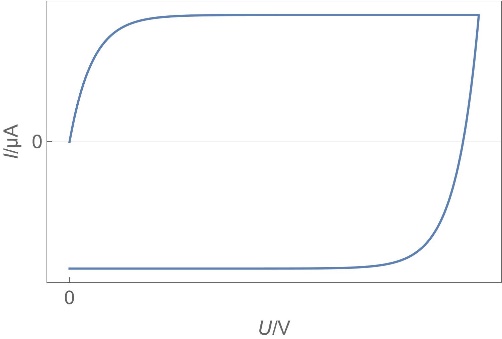 | 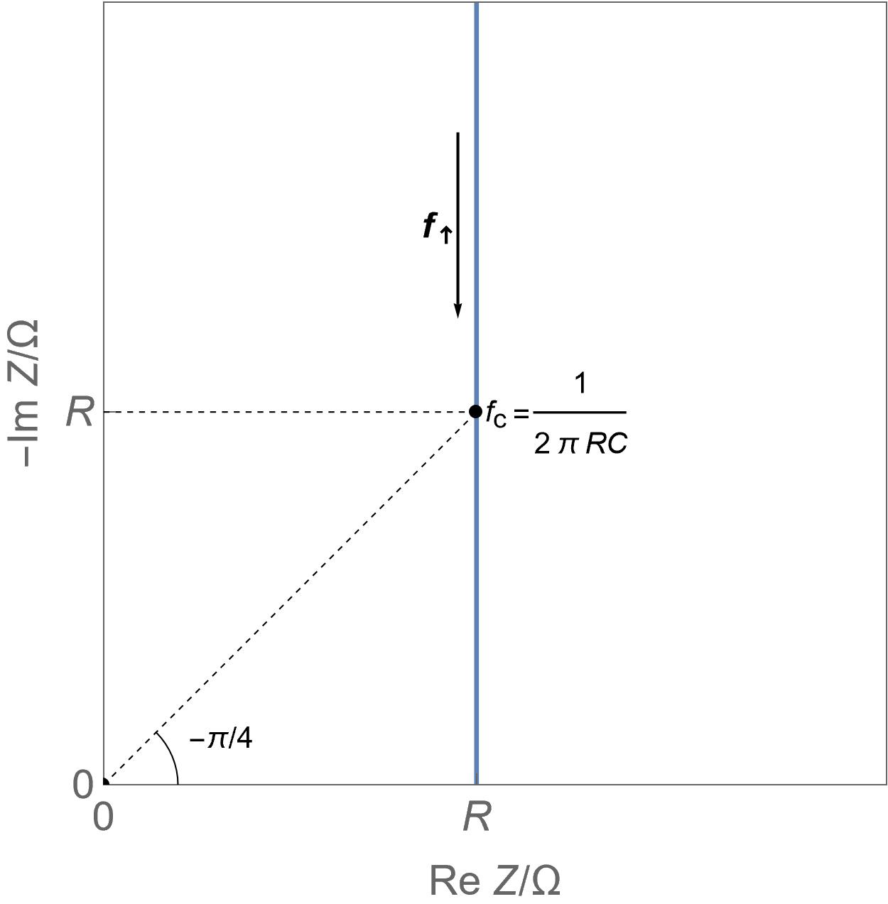 |
| EDLCs | High specific power, power storage, used in transportation. | Hundreds of F, few Wh/kg, few W/g | No | Yes, migration | Fast | Same as capacitor but larger current due to larger capacitance value | |
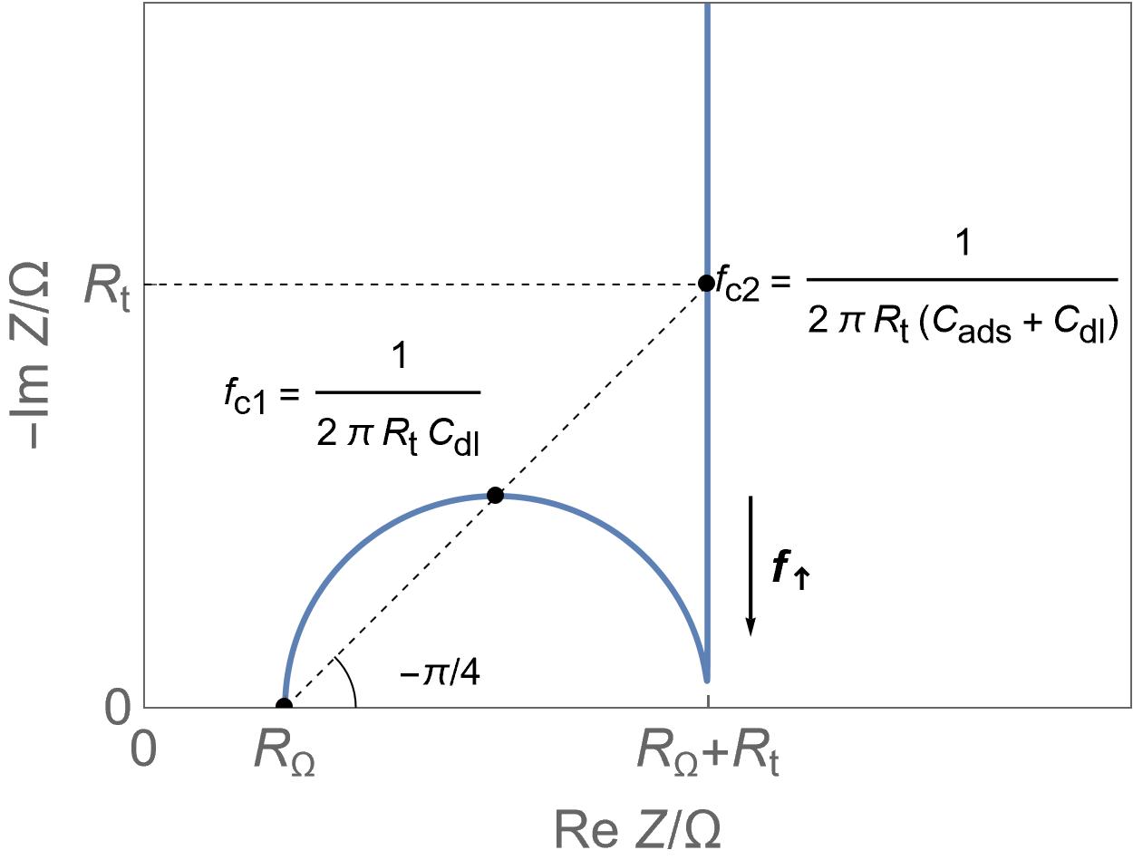
| Supercapacitors | High specific power, power storage, used in transportation. | Up to ten thousand F, few Wh/kg, few W/g | Yes | Yes, migration and possibly diffusion | Fast | 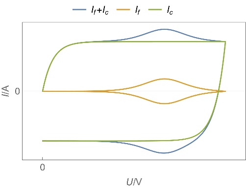 Homogeneous insertion process with double layer capacitance. One can see the various currents: capacitive, Faradaic and the sum of the two. Homogeneous insertion process with double layer capacitance. One can see the various currents: capacitive, Faradaic and the sum of the two. | 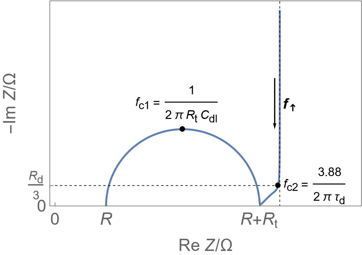 Restricted diffusion process in a very thin electrode. Restricted diffusion process in a very thin electrode.
|
| Insertion batteries | Energy storage | Capacity in mA·h or A·h for a single cell, hundreds of Wh/kg, around 1 W/g | Yes | Diffusion | Slow | 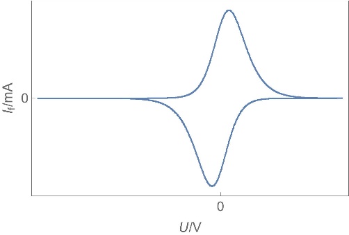 Linear direct insertion reaction, negligible ohmic drop and double layer capacitance and no phase transition. Linear direct insertion reaction, negligible ohmic drop and double layer capacitance and no phase transition. | 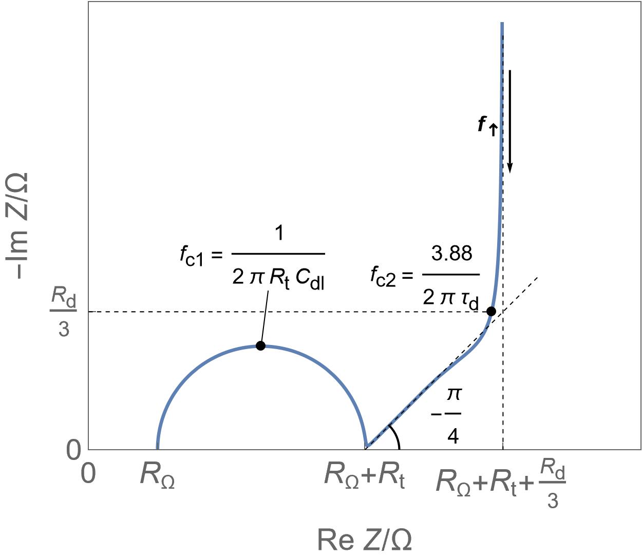 Linear restricted diffusion Linear restricted diffusion
|
 Homogeneous insertion process.
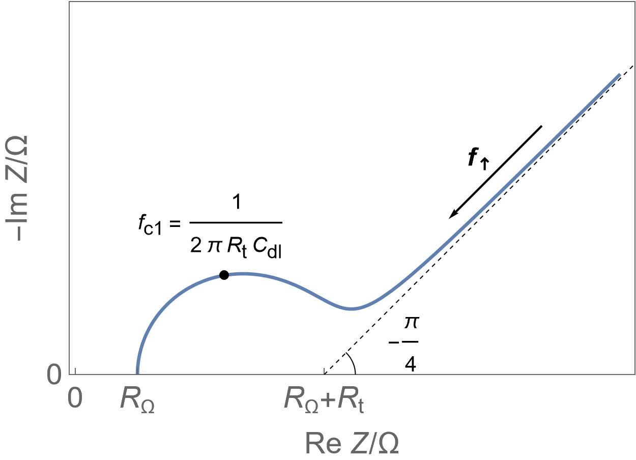 Semi-infinite diffusion
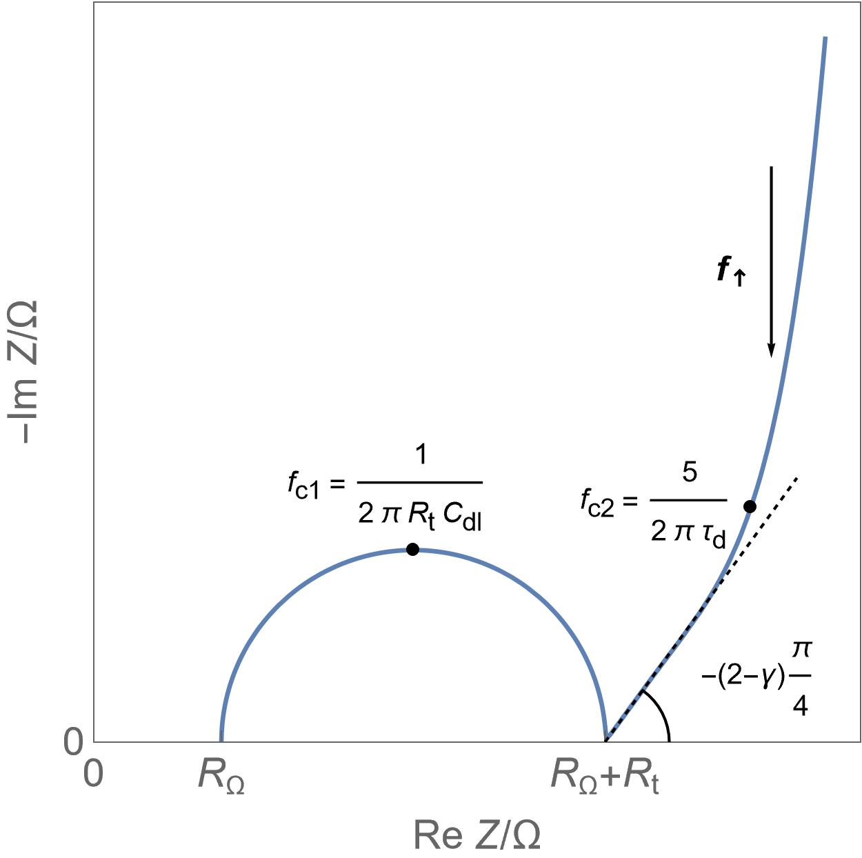 Anomalous or spherical diffusion
More detailed information can be found in [12].
References
[1] https://en.wikipedia.org/wiki/Capacitor
[2] B. E. Conway. Transition from “supercapacitor” to “battery” behavior in electrochemical energy storage. J. Electrochem. Soc., 1991 138 1539 – 1548
[3] P. Simon, Y. Gogotsi, B. Dunn. Where do batteries end and supercapacitors begin? Science, 2014 343 (6176) 1210-1211
[4] C. Costentin, T. R. Porter, J.-M. Savéant. How do pseudocapacitors store energy? Theoretical analysis and experimental illustration. ACS Applied Materials & Interfaces, 2017 9 (10) 8649-8658
[5] https://en.wikipedia.org/wiki/Capacitor_types
[6] M. Winter, R. J. Brodd. What are batteries, fuel cells, and supercapacitors ? Chem. Rev. 2004 104 4245-4269
[7] https://fr.wikipedia.org/wiki/Condensateur
[8] What is CV? A comprehensive guide to Cyclic Voltammetry
[9] J.-P. Diard, B. Le Gorrec, C. Montella, Cinétique Electrochimique, Hermann Editeurs, Paris 1996


